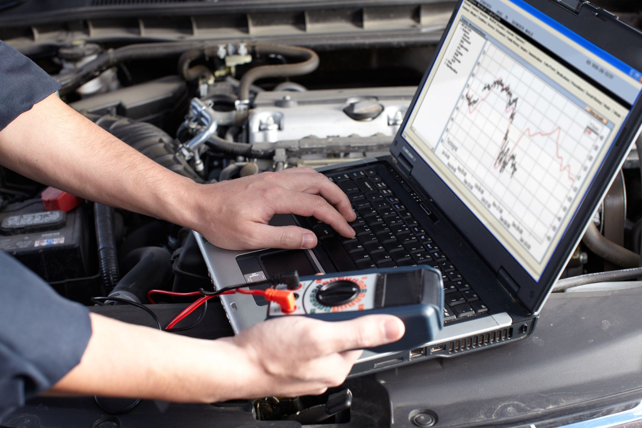
Range Rover
Electrical Services
The following guidelines are intended to ensure the safety of the operator whilst preventing damage to the electrical and electronic components fitted to the vehicle. Where necessary, specific precautions are detailed in the relevant sections of this document, reference to these precautions should be made prior to commencing repair operations.
Equipment - Prior to commencing any test procedure on the vehicle, ensure that the relevant test equipment is working correctly and any harnesses or connections are in good condition. This particularly applies to mains lead or connections.
WARNING: Before commencing work on an ignition system, all high tension terminals, adaptors and diagnostic equipment for testing should be inspected to ensure that they are adequately insulated and shielded to prevent accidental personal contact and to minimize the risk of shock. Wearers of surgically implanted pacemaker devices should not work in close proximity to ignition circuits or diagnostic equipment.
Polarity - Never reverse connect the vehicle battery and always observe correct polarity when connecting test equipment. High Voltage Circuits - Whenever disconnecting live ht circuits, always use insulated pliers and never allow the open end of the ht lead to come into contact with other components, particularly ECU's. Since high voltage spikes can occur on the terminals of the coil while the engine is running, exercise caution when measuring the voltage at these points
WARNING: The Xenon headlamp system generates up to 28,000 V and contact with this voltage could lead to fatality. Make sure that the headlamps are switched off before working on the system. Refer to the guidelines given in the 'General Information' section of the Service Repair Procedures Workshop Manual before any work is carried out.
Common symptoms
- fault messages such as alternator or gearbox failure.
- lights flashing even when switched off eg headlights and indicators flashing like a police car.
- windows, sunroof not working and/or cruise control not working.
- these expensive batteries are not lasting as long as they should (eg one year instead of seven).
- lots more examples of electrical things not working, fault messages, strange behaviour etc.
- most of these tests apply equally to all 12 volt cars but details have been specified for the P38 RR. P38 Range Rover electricals are very sensitive to voltage. You need a good strong alternator, clean earth points, healthy cables and a very strong battery. Testing takes about five minutes.
Battery Tests
- Turn the ignition key to the on position but DO NOT start the car.
- Turn on all electrical accessories (max heater blower, high beam lights, demister etc).
- Leave accessories on for 30 seconds.
- Turn off all accessories and turn key switch to the off position.
- Within one minute, measure battery voltage.
If the battery voltage is less than 12.5, the battery is not healthy. The battery may need to be replaced, however there is no point doing this before you are certain it is being charged properly. Weak charging circuits kill batteries pretty quickly. If you do need a new battery get a really good one (I no longer recommend Optima BTW)
When diagnosing an electrical fault, follow the steps below:
- Read the circuit description appropriate to the reported fault to ensure a good understanding of circuit operation.
- Study the power distribution, fuse details and earth distribution diagrams and identify other circuits which share fuses and/or earth points. Check whether these circuits operate correctly.
- Using the photographs contained in the Connector section, locate a point on the circuit (approximately half way between supply and earth) which is easily accessible.
- Check that the pin-out details of the connector are correct and that the correct signals exist at the correct terminals.
- Using a suitable non-permanent marker, mark the parts of the circuit you have verified.
- Continue to the next point on the circuit which is easiest to access and repeat the above.
- Continue with this approach until a fault is found, rectify the fault and then verify that the circuit operates correctly.
CAUTION: Never probe directly into the front face of a connector. This can damage the terminal and cause a failure. Always probe the back of a terminal, taking care not to damage the terminal or any seals. Never probe wire insulation. On small diameter cables this can cut the conductors. It may also allow moisture into the cable, causing corrosion
General, This document is intended to assist in diagnosing electrical faults, and should be used in conjunction with the Electrical Circuit Diagrams. The document is divided into the following sections.
- INTRODUCTION - Includes Electrical Precautions, a list of Abbreviations and general information on how to use this document.
- FUSE DETAILS - Provides details of location, rating in Amperes, and circuit(s) protected.
- EARTH POINTS AND HEADERS - Provides details of earth points and earth headers, including a plan view of the vehicle to aid location.
- DESCRIPTION AND OPERATION -Provides an explanation of how each of the systems operate.
- CIRCUIT REFERENCE NUMBERS -Provides a list of circuit reference numbers against a model or feature to which they apply.
- CONNECTOR DETAIL -Details of connectors including a location photograph, face view and pin-out table.
NOTE: Before starting electrical checks on the vehicle, ensure that relevant mechanical functions operate satisfactorily.